2026-11-20

A CNC machine cable assembly must maintain reliable power, control, and feedback connections under vibration, axis movement, coolant exposure, and electrical interference. The right configuration depends on the circuit function, installation route, and operating environment. A stationary cabinet connection and a moving machine-axis cable require different construction considerations.
For machine builders and OEM engineers, cable selection should begin with the electrical interface and physical installation conditions. Connector compatibility, conductor specifications, shielding, jacket material, and mechanical protection all influence long-term performance.
Cable routing determines whether an assembly experiences static installation, repeated bending, or torsional movement. Before selecting a cable, identify fixed sections, drag-chain travel, moving axes, and potential contact with machine guards or frames.
Dynamic applications require suitable conductor stranding, insulation, jacket flexibility, and strain relief. A cable intended for occasional repositioning may not withstand repeated machine travel.
Consider these installation differences:
| Installation type | Main requirements | Typical location |
|---|---|---|
| Stationary wiring | Electrical ratings, insulation and temperature resistance | Control cabinets |
| Linear movement | Dynamic bend radius, flex resistance and jacket durability | CNC drag chains |
| Rotary or torsional movement | Torsion resistance and controlled cable routing | Multi-axis equipment |
| Exposed machine routing | Abrasion, coolant and environmental resistance | External machine connections |
For moving sections, verify the manufacturer's dynamic bend radius and permitted operating conditions. The cable should also have sufficient free length throughout the complete axis travel.
Detailed continuous-motion considerations are covered in this high-flex industrial cable selection guide.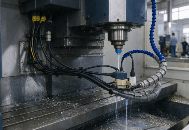
CNC equipment uses different cable types to connect motors, drives, encoders, sensors, and controllers. Their electrical requirements should be evaluated separately rather than treating every connection as a general-purpose industrial cable.
| Cable function | Important specifications | Selection priority |
|---|---|---|
| Motor power | Conductor size, voltage, current and insulation | Electrical capacity and mechanical durability |
| Encoder feedback | Pair arrangement, pin mapping and shielding | Signal integrity |
| Control and sensor | Conductor count, voltage and connector configuration | Accurate signal transmission |
| Industrial communication | Data transmission characteristics and shielding | Network compatibility |
Motor power cables must accommodate the expected current and voltage while maintaining suitable insulation performance.
Encoder cables require correct conductor pairing, pin assignments, and shield termination. A connector that physically fits does not necessarily guarantee electrical compatibility.
For feedback applications, review the dedicated industrial encoder cable assembly guide. It covers interface compatibility, wiring maps, and signal-related selection factors.
Spindle drives, servo motors, contactors, and switching power supplies can introduce electromagnetic interference into nearby circuits. This can affect sensitive feedback and communication signals when cable routing and shielding are inadequate.
A suitable EMC design should consider:
Shielded cable construction for relevant signal and power circuits.
Consistent shield termination according to the machine's grounding design.
Separation between sensitive signal cables and high-current conductors.
Appropriate connector backshells and shield bonding arrangements.
Cable routing that avoids unnecessary parallel runs near interference sources.
Shielding alone does not guarantee interference protection. Grounding, termination, cable separation, and the overall machine design must work together.
The outer jacket also needs to match the machine environment. CNC cables may encounter cutting fluids, lubricants, metal chips, abrasion, and temperature fluctuations.
PVC, PUR, and other jacket materials have different mechanical and chemical characteristics. Confirm compatibility with the actual coolant formulation and cleaning process rather than relying on a general oil-resistance description.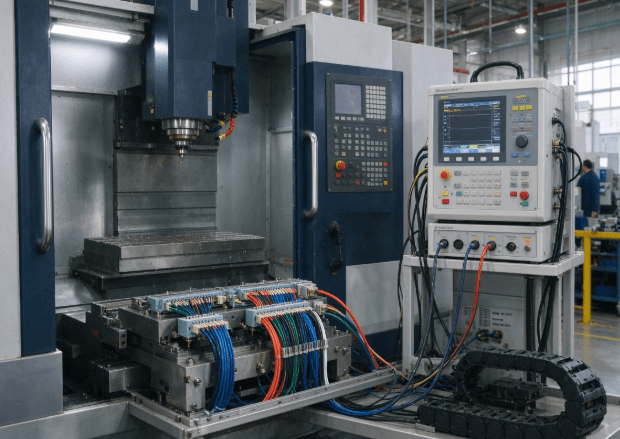
Installation quality affects cable reliability even when the selected assembly meets its electrical specifications.
Before releasing a cable assembly for machine integration, review the following:
Connector keying, gender, and pin assignments.
Cable length and clearance at both travel extremes.
Minimum bend radius along the complete route.
Clamp positions and strain-relief arrangements.
Shield continuity and grounding connections.
Protection against sharp edges, abrasion, and coolant exposure.
Avoid tight cable ties or installation bends that deform the jacket. Connector exits also need sufficient clearance to prevent localized mechanical stress.
A project-specific validation plan may include continuity, open-circuit and short-circuit checks, insulation resistance where specified, shield continuity, connector retention, and representative movement testing.
Each test should have documented conditions and acceptance limits. A basic electrical test confirms defined connections but does not establish long-term dynamic durability.
SOAR's industrial cable collection includes cable assemblies for automation equipment, industrial machinery, and control applications.
Several listed products provide useful examples of different CNC-related connection requirements:
Motor power extension cable
The DB9W4 shielded RST motor power extension cable features male and female DB9W4 connectors and a listed standard length of 4 meters, with custom length options.
Encoder connection cable
The DB15 shielded encoder cable assembly uses male and female DB15 connectors. Its listed standard length is 70 cm, with custom length options.
These products illustrate different industrial connection configurations. Their specifications should not be interpreted as universal compatibility with every CNC controller or motor.
For OEM applications, confirm the connector drawing, pinout, electrical ratings, cable construction, and installation conditions before approving a configuration.
It depends on the cable's documented dynamic performance. Its bend radius, jacket construction, and flex qualification must meet the actual movement conditions.
No. Shielding helps reduce electromagnetic coupling, but correct grounding, termination, and cable separation are also important.
This depends on the electrical architecture and EMC requirements. Power and feedback circuits need appropriate separation and insulation arrangements.
Common checks include continuity, open and short circuits, insulation resistance where specified, shield continuity, connector retention, and application-specific movement testing.
Incorrect length can create excessive tension, tight bends, interference with moving components, or unnecessary cable loops. Length should be checked throughout the complete machine travel.
International Electrotechnical Commission (IEC) — IEC 60204-1: Safety of Machinery – Electrical Equipment of Machines. Provides a framework for electrical equipment requirements in machinery.
Wire Harness Manufacturers Association (WHMA) — IPC/WHMA-A-620. Provides cable and wire harness workmanship and acceptance guidance.
SOAR Technology — Industrial Cable Product Collection. Provides examples of industrial power, encoder, and connection cable assemblies.