Learn the fundamentals of GPS antenna cables, including their critical functions, physical architecture, and how material selection impacts RF signal loss and system performance.
The precision of a Global Positioning System (GPS) relies on a remarkably faint signal traveling from medium earth orbit to a receiver on the ground. By the time a satellite signal reaches an antenna, its power level is often below the thermal noise floor. In this high-stakes RF (Radio Frequency) environment, the GPS antenna cable is not merely a "wire" but a precision-engineered transmission line.
For engineers and project managers, understanding the interplay between cable attenuation, shielding, and impedance is vital to ensuring that the receiver can successfully "lock" onto satellite data without interference or signal degradation.
The Critical Role: Understanding GPS Cable Function
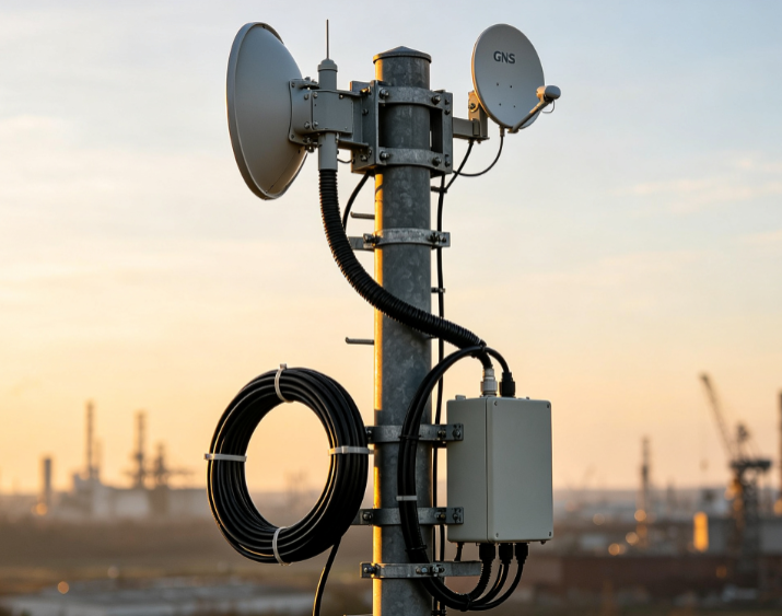
The primary GPS cable function is to transport RF energy from the antenna to the receiver unit with minimal distortion and loss. In most industrial and automotive setups, the system utilizes an active antenna—one that includes a Low Noise Amplifier (LNA).
In these configurations, the coaxial cable performs a dual role:
- Downlink Path: It carries the high-frequency GPS signals (typically L1 at 1575.42 MHz or L2 at 1227.60 MHz) from the antenna to the receiver.
- Uplink DC Power: It carries a small DC voltage (phantom power) from the receiver back up to the antenna to power the integrated LNA.
If the cable is poorly shielded or improperly matched, the Signal-to-Noise Ratio (SNR) drops. This results in longer Time-to-First-Fix (TTFF) or, in extreme cases, a complete inability to maintain a position fix in "canyon" environments or high-interference zones.
Physical Architecture of a GPS Antenna Cable
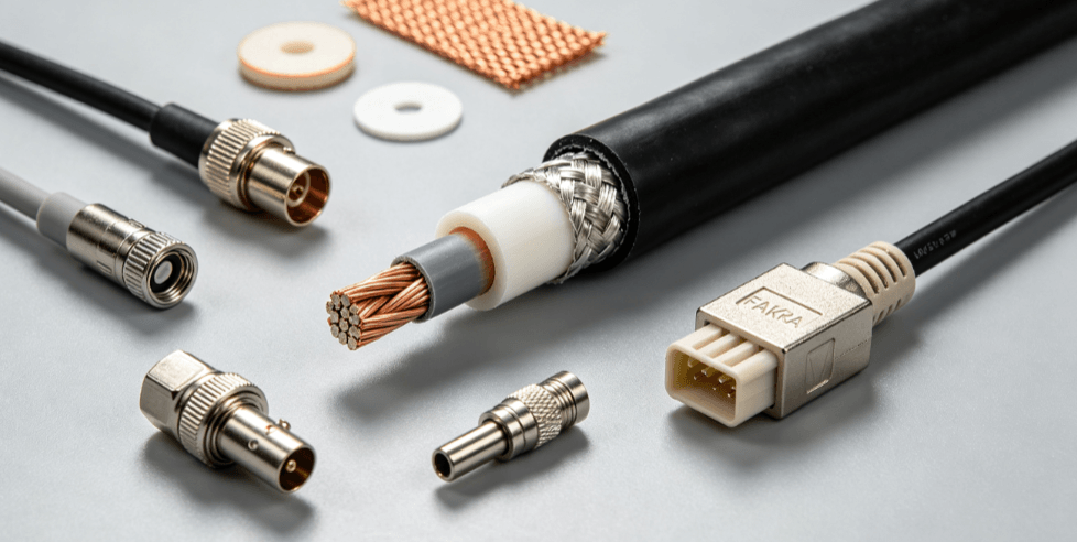
A standard GPS cable is coaxial, meaning it shares a geometric axis for its internal components. Each layer is designed to solve a specific physics problem related to electromagnetics.
- Center Conductor: Usually made of solid copper or copper-clad steel (CCS). In high-vibration environments, stranded conductors are preferred for flexibility, though they exhibit slightly higher attenuation.
Dielectric Insulator: This layer surrounds the conductor and determines the cable’s impedance and velocity of propagation. High-quality materials like Polytetrafluoroethylene (PTFE) or Foam Polyethylene (PE) are used to minimize signal absorption.
- Shielding (Outer Conductor): This is the "defense" layer. It typically consists of a metallic foil wrapped in a woven braid. It prevents external EMI (Electromagnetic Interference) from entering the signal path and keeps the RF signal contained.
- Outer Jacket: The skin of the cable. For outdoor or automotive use, jackets are made of UV-stabilized PVC or LSZH (Low Smoke Zero Halogen) to withstand environmental degradation.
-
Key Performance Metrics for RF Selection
When evaluating a GPS antenna cable for a project, engineers focus on four primary technical specifications.
| Metric |
Importance |
Real-World Impact |
| Characteristic Impedance |
Must be 50 Ohms. |
Mismatched impedance causes signal reflections (VSWR), leading to power loss. |
| Attenuation (Loss) |
Measured in dB per meter/foot. |
Higher loss reduces the effective gain of the antenna, weakening the link budget. |
| Shielding Effectiveness |
Measured in dB. |
Higher values (e.g., >90dB) prevent cellular or Wi-Fi signals from "leaking" into the GPS line. |
| Bending Radius |
Physical limit of curvature. |
Exceeding the radius can kink the internal shield, permanently altering impedance. |
Common Coaxial Standards in GPS Applications
Not all coaxial cables are suitable for GPS frequencies. Since GPS operates in the L-band (1–2 GHz), the cable must be rated for high-frequency performance.
1. RG-174 (Thin & Flexible)
Commonly used for short internal runs or consumer-grade magnetic mount antennas. While highly flexible and easy to route through tight spaces, it has relatively high attenuation. It is generally not recommended for cable runs exceeding 3–5 meters.
2. RG-58 (Standard Industrial)
A thicker cable than RG-174, offering a better balance between flexibility and signal loss. It is a staple in professional fleet management and marine GPS installations where the cable length is moderate.
3. LMR® Series (Low Loss)
Cables like LMR-100A or LMR-200 are designed specifically for high-performance RF. They utilize a solid center conductor and high-performance shielding. Manufacturers like Soar Cable often recommend these for infrastructure or critical telecommunications where signal integrity cannot be compromised over longer distances.
Connector Interfaces: Ensuring a Proper Mate
The GPS antenna cable is only as good as its termination. The choice of connector is usually dictated by the receiver hardware and the environment.
- SMA (Sub-Miniature A): The industry standard for many GPS receivers. It features a threaded interface that provides a secure, vibration-resistant connection.
- MCX/MMCX: Snap-on connectors used in compact electronics or handheld devices where space is at a premium.
- FAKRA: Standard in the automotive industry. These are color-coded and mechanically keyed to prevent incorrect installation on assembly lines.
Engineering Considerations for Installation
In industrial manufacturing and OEM projects, the environment dictates the cable's lifespan.
- Signal Loss Compensation: If a long cable run is unavoidable (e.g., from a ship's mast to the bridge), a high-gain active antenna must be used to overcome the "line loss" of the cable.
- Moisture Ingress: Water is the enemy of RF. If moisture enters the dielectric, the impedance changes instantly. Using IP67-rated connectors or heat-shrink tubing at termination points is a standard manufacturing requirement.
- Phase Stability: In advanced applications like RTK (Real-Time Kinematic) positioning, the phase of the signal matters. In these cases, cables must be phase-stable under varying temperatures to maintain centimeter-level accuracy.
Selecting the Right Integration Partner
Choosing a GPS antenna cable involves balancing mechanical constraints with electrical requirements. For OEMs and system integrators, working with a specialized manufacturer allows for the customization of cable lengths and connector types to match specific housing requirements.
Companies such as Soar Cable provide engineered solutions that account for shielding effectiveness and environmental durability, ensuring that the critical GPS link remains robust from the factory floor to the end-user environment.
FAQ
Q: Can I use a standard TV coaxial cable (RG-6) for a GPS antenna?
A: No. Standard TV cables are typically 75 Ohm, whereas GPS systems are designed for 50 Ohm impedance. Using 75 Ohm cable will cause significant signal reflection (VSWR) and may damage the receiver’s LNA power supply.
Q: How does cable length affect GPS accuracy?
A: Length itself doesn't directly decrease "accuracy," but it increases "attenuation." If the cable is too long, the signal becomes too weak for the receiver to process. This leads to a loss of satellite tracking, which increases the margin of error in positioning.
Q: Is a thicker GPS cable always better?
A: Generally, thicker cables have lower loss because they have a larger center conductor. However, they are less flexible and harder to route. The "best" cable is the one that meets your link budget (signal loss) requirements while fitting within your mechanical space constraints.
Q: What is the difference between a passive and an active GPS cable setup?
A: The cable itself remains the same, but in an "active" setup, the cable must be capable of carrying a DC current to power the antenna's amplifier. Most high-quality 50 Ohm coaxial cables handle this DC bias without issue.
Reference Sources
- IEEE Xplore: Analysis of Signal Loss in Coaxial Transmission Lines at L-Band Frequencies. ieee.org
- IPC-A-620 Standards: Requirements and Acceptance for Cable and Wire Harness Assemblies. ipc.org
- MIL-DTL-17: General Specification for Radio Frequency Coaxial Cables. quicksearch.dla.mil
- GPS World: The Impact of Signal-to-Noise Ratio on GNSS Receiver Performance. gpsworld.com


