Master the fundamentals of GPS antenna cables. Explore how cable construction, impedance, and connector types like SMA and Fakra impact GNSS signal performance.
Understanding the Critical Role of the GPS Antenna Cable
In the world of Global Navigation Satellite Systems (GNSS), the antenna often gets the spotlight, but the cable connecting it to the receiver is the unsung hero of signal integrity. A GPS antenna cable is a specialized Radio Frequency (RF) coaxial line designed to transport extremely weak signals—often arriving from satellites at levels as low as -130 dBm to -160 dBm—from the antenna to the processing unit without introducing excessive noise or loss.
For engineers, OEM project managers, and RF technicians, selecting the right cable isn't just about length; it is about managing the link budget. If the cable is poorly matched or constructed, the most advanced GPS module in the world will struggle with "No Fix" errors, high TTFF (Time to First Fix), or degraded positioning accuracy.
What is a GPS Antenna Cable and How Does It Function?
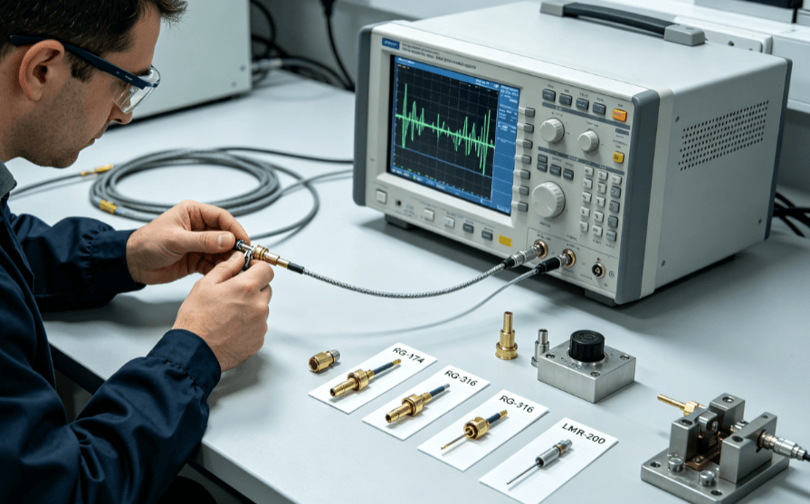
The primary gps cable function is to act as a controlled-impedance transmission line. Unlike standard electrical wires that carry low-frequency power, GPS signals operate in the L-band (primarily L1 at 1575.42 MHz and L2 at 1227.60 MHz). At these high frequencies, the signal does not just flow through the wire; it travels as an electromagnetic wave between the inner conductor and the outer shield.
The cable serves three specific purposes:
- Signal Transmission: Efficiently moving the RF energy from the antenna to the receiver.
- Power Delivery: In many "Active Antenna" setups, the cable carries a DC voltage (usually 3.3V or 5V) from the receiver back up to the antenna's Low Noise Amplifier (LNA).
- Interference Shielding: Protecting the weak satellite signal from external EMI (Electromagnetic Interference) caused by nearby cellular, Wi-Fi, or automotive electronics.
The Anatomy of a High-Performance RF Cable Assembly
To maintain signal integrity, GPS cables (typically coaxial) consist of four distinct layers. Understanding these materials is essential for evaluating cable quality in industrial or automotive environments.
| Component |
Material Options |
Function |
| Inner Conductor |
Solid Copper or Copper Clad Steel (CCS) |
Carries the signal and DC power. Solid copper offers the lowest resistance. |
| Dielectric Insulator |
PE, PTFE, or FEP |
Maintains the physical spacing between the core and shield, determining the cable’s impedance. |
| Shielding |
Tinned Copper Braid + Aluminum Foil |
Prevents signal leakage and blocks external noise. Double-shielding is preferred for GPS. |
| Outer Jacket |
PVC, PE, or LSZH |
Protects the cable from UV, moisture, and mechanical abrasion. |
In precision manufacturing, such as the RF assemblies found at SoarCable, the consistency of the dielectric and the density of the braid are tightly controlled. Even a minor deviation in the cable's diameter can shift the impedance away from the standard 50 Ohms, leading to signal reflections known as VSWR (Voltage Standing Wave Ratio).
Common Cable Types for GNSS Applications
Not all coaxial cables are suitable for GPS. The choice depends on the balance between flexibility, diameter, and "attenuation" (signal loss per meter).
- RG-174: The industry standard for short runs (1-3 meters). It is highly flexible and thin (approx. 2.8mm), making it ideal for vehicle dashboards and handheld devices. However, it has higher signal loss than thicker cables.
- RG-316: A high-temperature alternative to RG-174, often featuring a PTFE dielectric. It is preferred in industrial machinery where heat resistance is mandatory.
- LMR-100/LMR-200: "Low Loss" cables that utilize a foil/braid combination. These are used when the distance between the antenna and receiver exceeds 5 meters, as they preserve more of the signal than standard RG-series cables.
Connector Standards: Choosing the Right Interface
The connector is the most common point of failure in a GPS system. Selecting the right interface depends on the application environment:
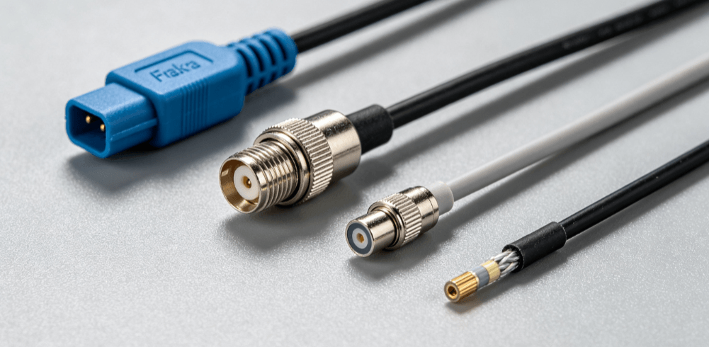
- SMA (Sub-Miniature A): The most common connector for industrial and IoT GPS receivers. It features a threaded interface that provides a secure, vibration-resistant connection.
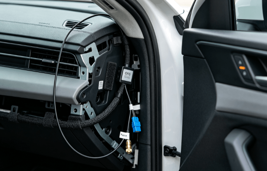
- Fakra: The standard for the automotive industry. These are color-coded (Blue for GPS) and feature a plastic housing with a locking clip to prevent disconnection in high-vibration vehicle environments.
- MCX / MMCX: Micro-miniature connectors used in compact consumer electronics or internal PCB connections where space is at a premium.
- U.FL (IPEX): Ultra-miniature connectors found on the surface of GPS modules. These are delicate and typically intended for "set and forget" internal installations.
Critical Performance Metrics for Engineers
When reviewing technical datasheets for GPS antenna cables, three metrics dictate real-world performance:
1. Attenuation (Signal Loss)
Measured in dB/meter. For a GPS L1 signal (1.5 GHz), an RG-174 cable might lose about 1.2 dB per meter. If your cable run is 5 meters, you lose 6 dB—effectively cutting your signal strength by 75% before it even reaches the receiver.
2. Velocity of Propagation (VoP)
This is the speed at which the signal travels through the cable relative to the speed of light. High-quality dielectrics (like PTFE) offer higher VoP, which is critical for timing-sensitive GPS applications like network synchronization.
3. Bending Radius
In tight installations (like aerospace or automotive pillars), exceeding the minimum bend radius can "kink" the internal dielectric. This changes the cable's impedance at the bend point, causing signal reflections that degrade the GPS fix.
Best Practices for Installation and Integration
- Keep it Short: Always use the shortest cable possible to minimize attenuation. If a long run is unavoidable, switch to a lower-loss cable like LMR-200 or an active antenna with high LNA gain.
- Avoid Tight Coils: Excess cable should be laid in a loose "figure-eight" or trimmed to size. Coiling cable tightly can create an inductor effect and increase interference.
- Check the Impedance: Ensure all components (antenna, cable, and receiver) are 50 Ohms. Mixing with 75 Ohm (video/CATV) equipment will result in significant signal loss.
- Environmental Sealing: For outdoor antennas, ensure connectors are sealed with heat-shrink tubing or IP-rated housings to prevent moisture ingress, which can corrode the copper shielding over time.
Conclusion
The GPS antenna cable is more than just a wire; it is a precision-engineered component of the RF signal chain. By understanding the trade-offs between cable types like RG-174 and LMR-200, and ensuring the use of high-quality connectors like SMA or Fakra, you can ensure your GNSS system maintains a robust, reliable lock in even the most challenging environments. Whether for autonomous vehicles or industrial IoT, the "basics" of cabling often determine the success of the entire system.
FAQ
Q: Can I use a standard TV coaxial cable (RG-6) for my GPS antenna?
A: No. Standard TV cables are 75 Ohm, while GPS systems are designed for 50 Ohm impedance. Using the wrong impedance will cause signal reflections (VSWR), leading to poor performance or no signal fix.
Q: How long can a GPS antenna cable be before the signal is lost?
A: This depends on the cable type and whether the antenna is active (powered). For a passive antenna using RG-174, signals usually degrade significantly after 2-3 meters. With an active antenna and low-loss cable (like LMR-400), runs can extend beyond 20-30 meters.
Q: What is the difference between a male and female SMA connector for GPS?
A: A standard SMA Male has internal threads and a center pin. An SMA Female has external threads and a center sleeve. Note: Some GPS equipment uses "RP-SMA" (Reverse Polarity), which swaps the pin and sleeve—always verify the center pin configuration before purchasing.
Q: Does the cable color matter for GPS?
A: Generally, no, unless you are using Fakra connectors. In the automotive industry, Fakra "C" connectors are blue and specifically designated for GPS/GNSS to prevent assembly errors on the production line.
Reference Sources


